Protected: LM358 Oscillator (Arduino code)
Protected: RC time constant lab – Arduino code
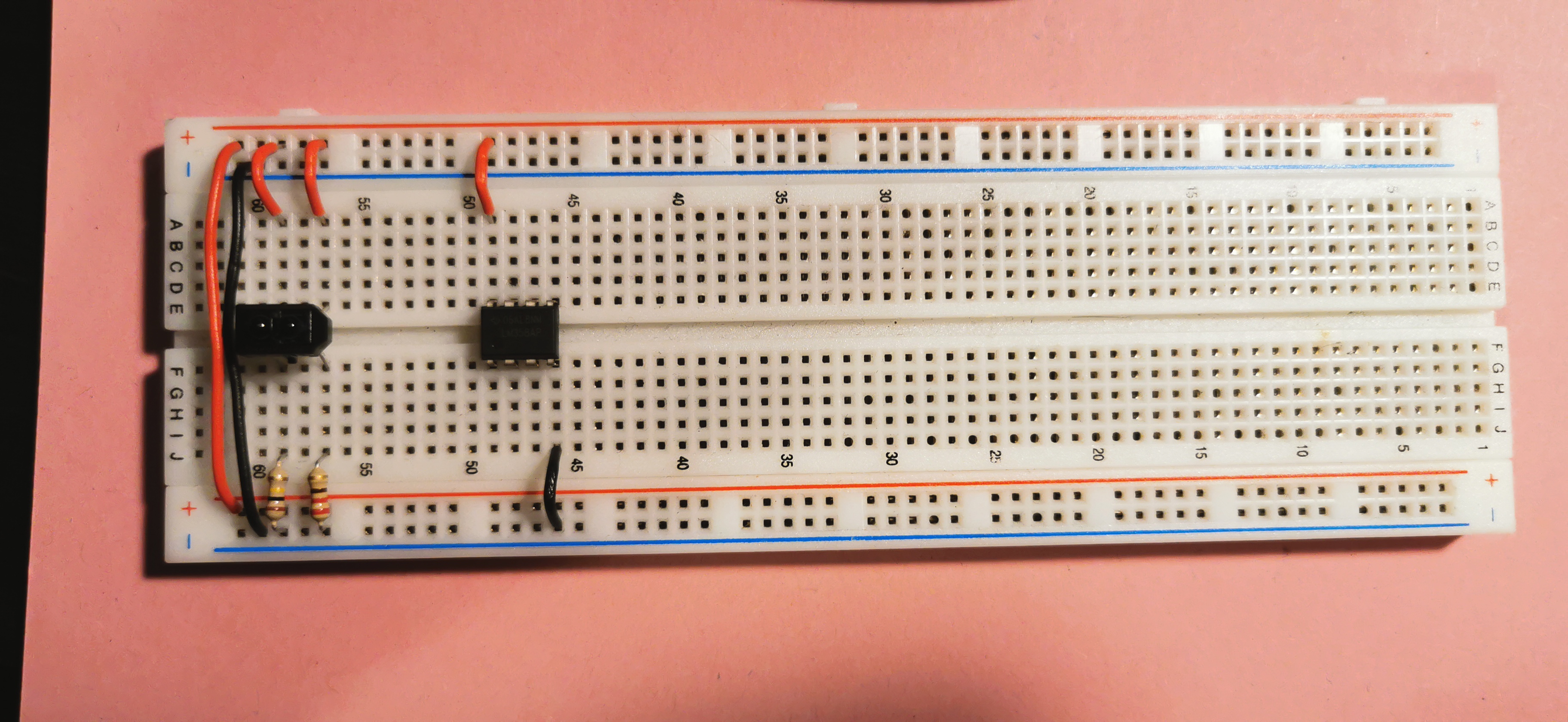
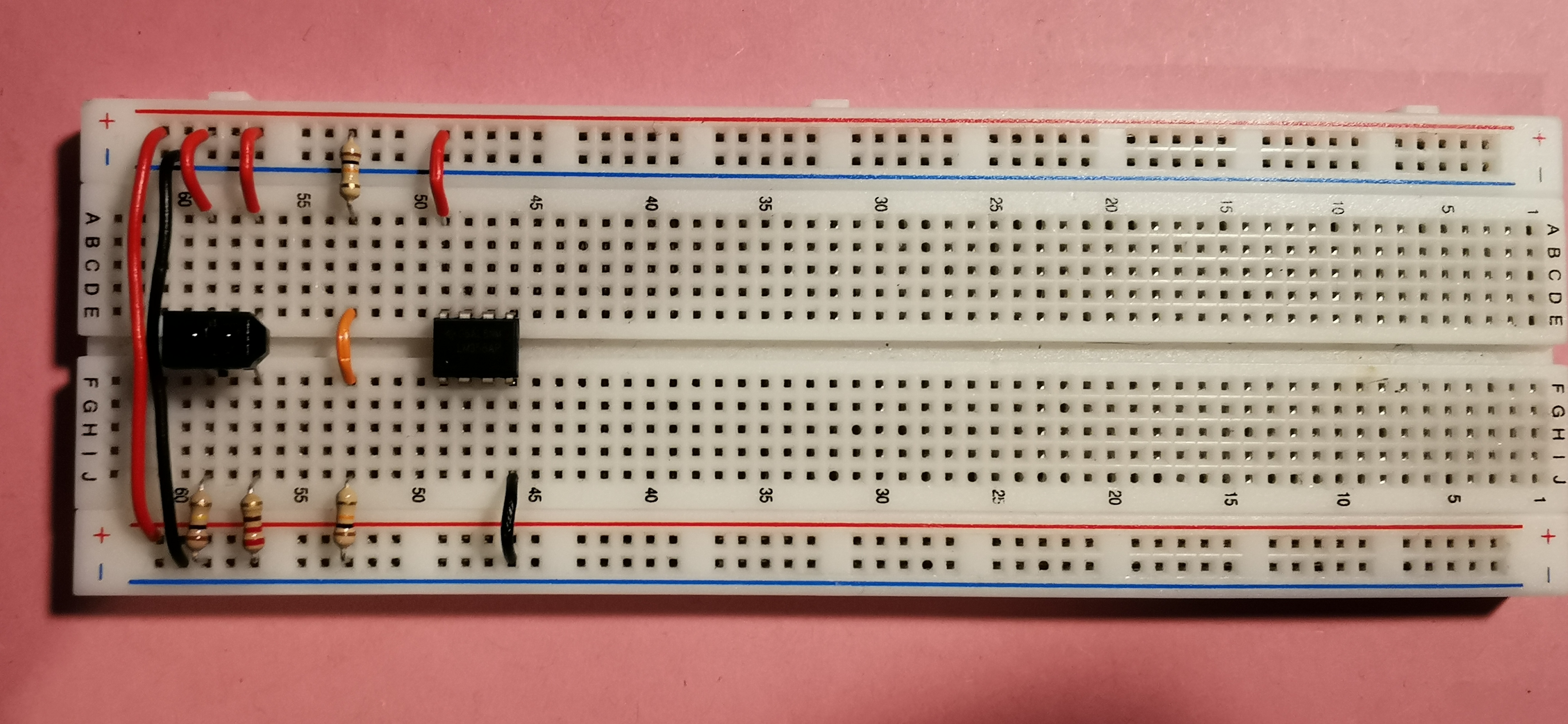
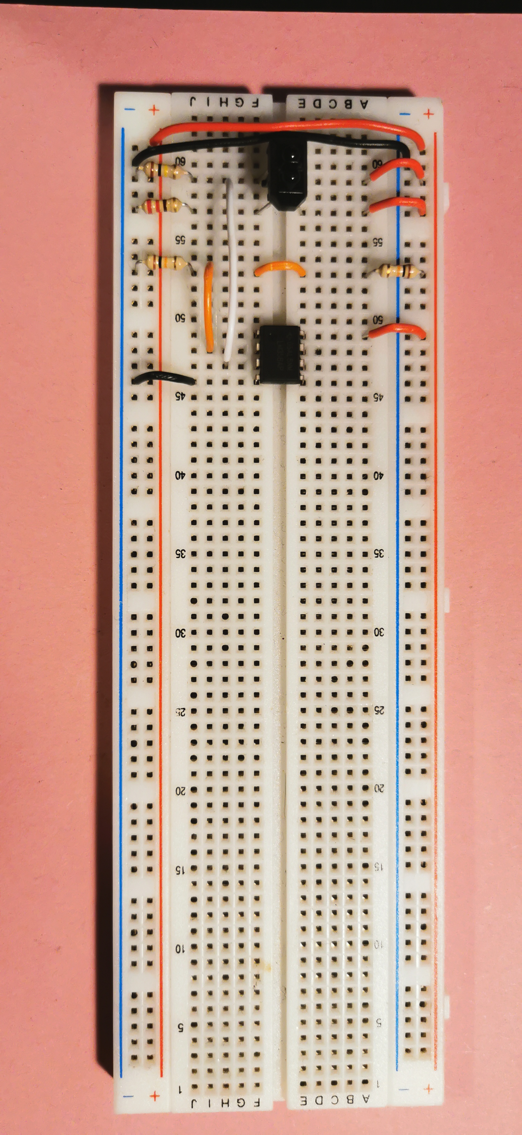
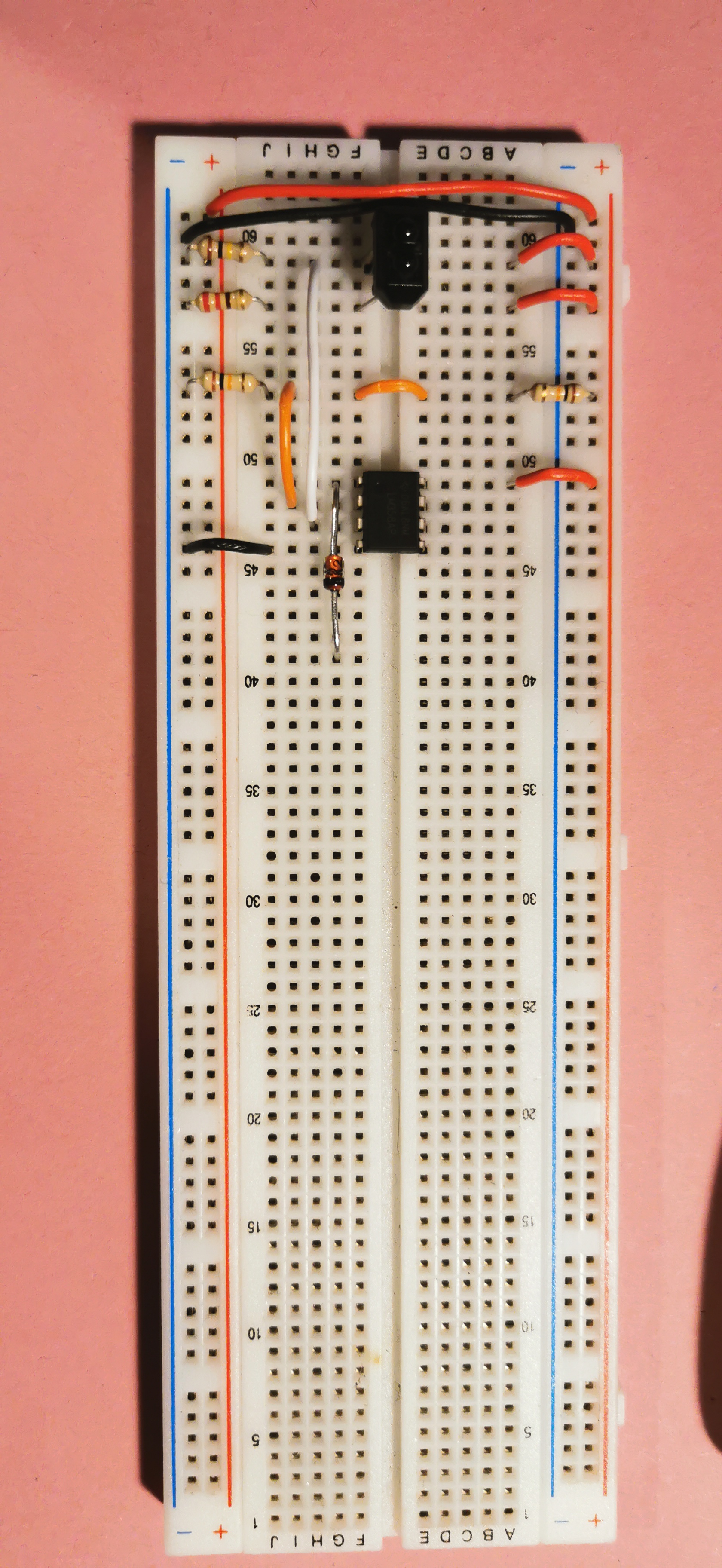
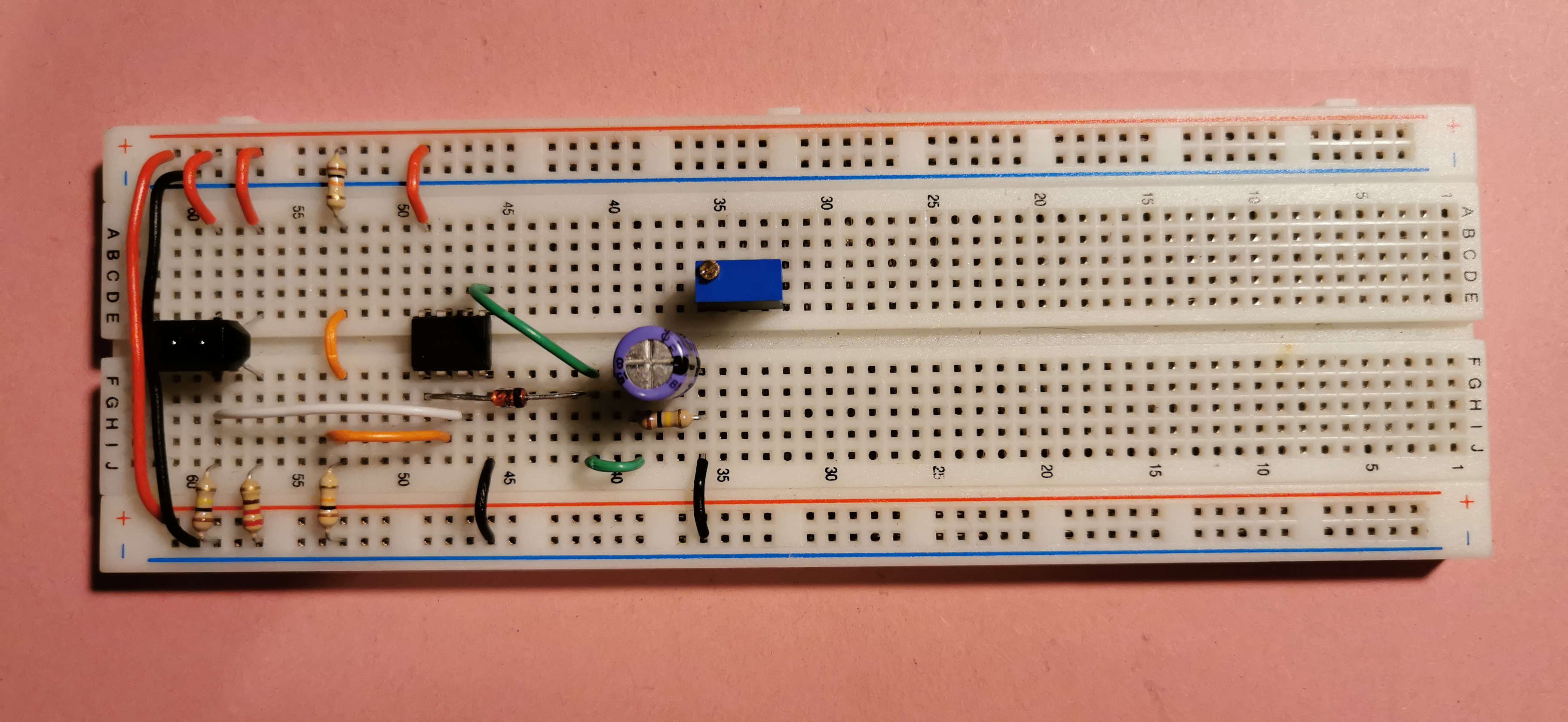
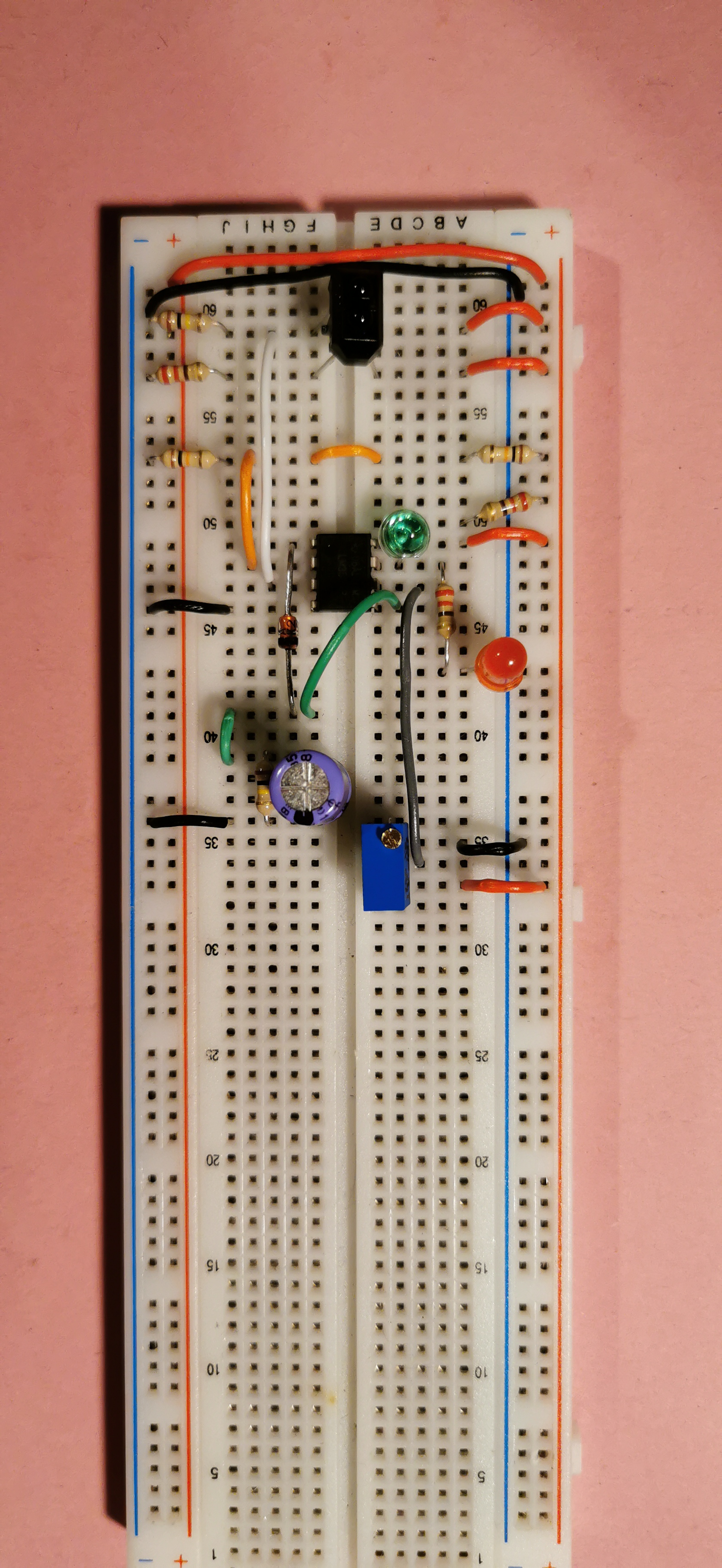
Pulse stretcher photographs
Sequence of photographs to help with the construction of the pulse stretcher circuit.


Multiple cameras using OBS and Iruin
I’ve been teaching from home this semester and I’ve been trying to find the setup that allows for multiple cameras, easy scene switching, and quick recording of material where necessary.
One of the biggest problems I’ve had is finding a way to switch between multiple cameras when using programs such as MS Teams, Skype, Zoom, Bongo etc. to deliver a class. This is a work in progress for me but I thought I’d share what I have found works best for me, but this is sure to change over the next while as I am still ironing out problems.
The setup I’d like to have is made up of the following parts. The laptop webcam is used to show my face for conversations. This is useful for meetings and conversations with students. No major problems there. Sharing documents, presentations, or programs is also achievable in most of the mentioned programs.
One of the classroom “devices” I am trying to replicate on camera is a whiteboard environment. I find this to be the best way to sketch out ideas and to help develop an understanding of what is being discussed at the time. For this, I need a downward-facing camera (which is my phone’s camera) that is looking down on an A4 page, for example. The setup I have at the moment is shown below.


Accessing a single camera is easy to do, but having access to all of these sources and with the ability to easily switch between them can be cumbersome in some programs. To overcome this problem I’ve used the following setup.
- Iriun – This allows me to use my phone’s camera as a wireless or wired webcam on a PC/Mac/Ubuntu.
- Open Broadcaster Software (OBS): This is a free and open source software for video recording and live streaming. It has an option called “virtual camera” that allows you to output the current video stream as another webcam device on your computer.
Phone camera as a webcam
I decided to use my phone’s camera to view the whiteboard area. The phone’s camera wouldn’t show as a camera device on my computer automatically. I was pointed towards Iruin as a possible solution to this problem (thanks Dan!). When Iruin is installed on a phone and computer that are both connected to the same WiFi network, the phone’s cameras (yes, cameras!) will then show as camera devices on the computer. The app’s icon is shown in the screenshot from my phone.

When the phone is successfully connected to the computer the following interface is presented which allows you to set different resolutions (This resolution option was available on Windows but not on macOS).

With this much done your phone should now be available to use as a camera input device on all your programs that allow camera devices.
Setting up OBS
Once you are happy that you have your phone connected to your computer, the next step is to install OBS. When you open OBS for the first time, you will be asked about a number of different options, I kept everything as default and choose “recording” to be the main use of the program.
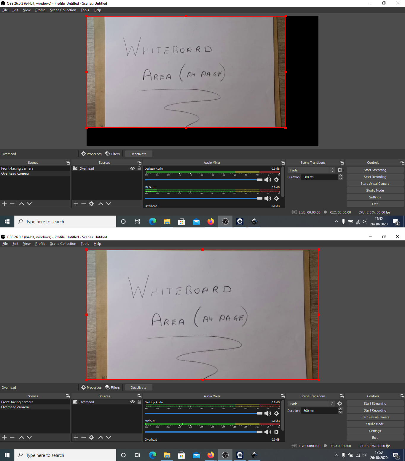
The main page of OBS is shown below. There a number of different activities that can be completed using OBS but for this tutorial I am going to stick to getting the two cameras setup for use in MS Teams, Skype, etc.

The way I approach setting up OBS for myself is I create a “scene” for each camera scenario. The first scene I create will use my front-facing webcam as a source. Sources act as inputs for different scenes and these can be audio and/or video, as well as a number of other options, but I am going to keep it simple here.
I renamed “Scene 1” (right click and choose rename) as “Front-facing camera”, and added (click small “+” sign under Sources) a “Video Capture Device”.
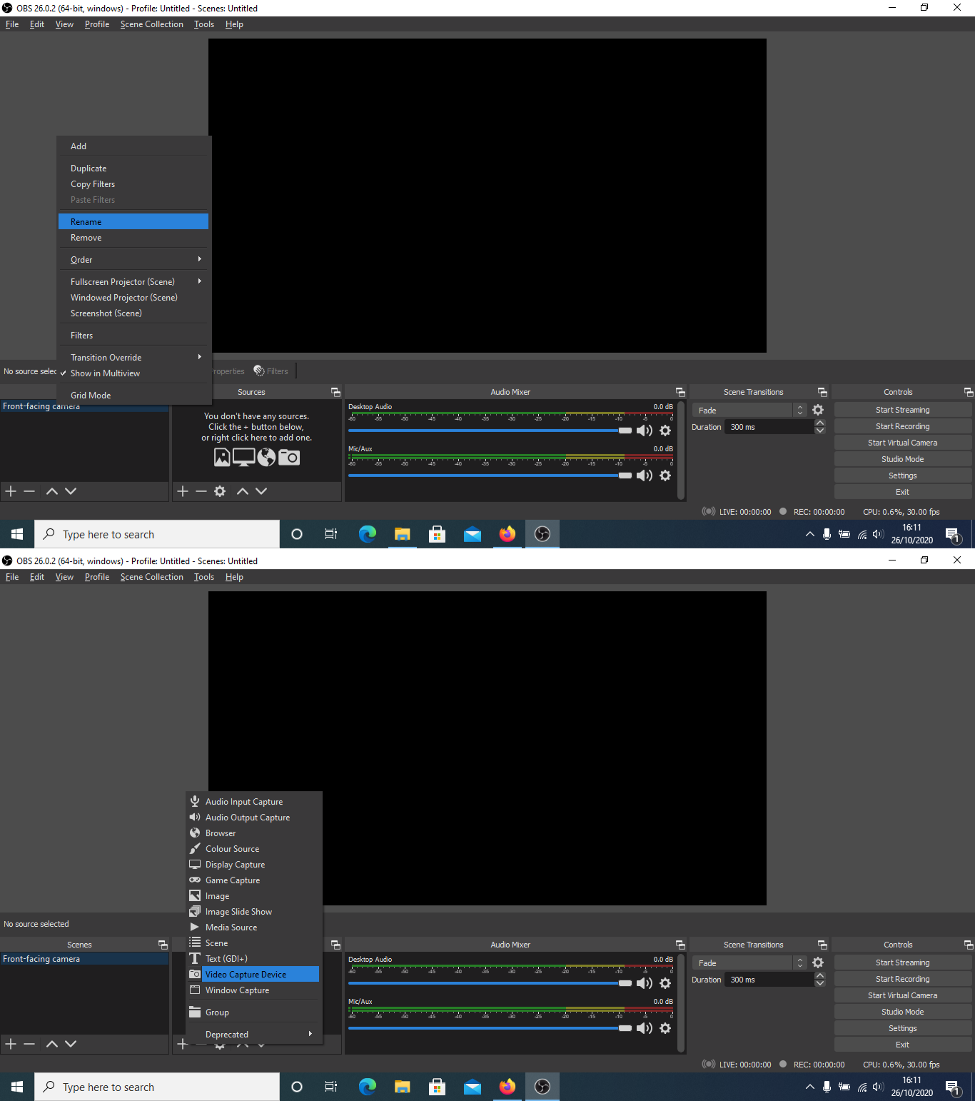
As this is my first time setting up OBS I need to create a new source (this one will be my computer’s webcam) which I named “Webcam”. The next dialog box allows you to select the device that will be used for “Webcam”, and I am selecting my computer’s integrated webcam. A preview should show up and additional setting can be changed here.
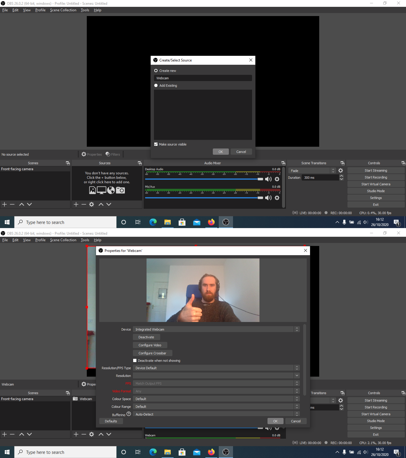
At this point your OBS interface should resemble the following image (but with you instead of me). The red frame can be used to adjust the size of the webcams video stream as it sits on the overall “canvas” used in OBS.

Next step is to setup an additional scene that will be used for the overhead camera. I added a new scene (click the small “+” sign under Scenes) and rename “Scene 2” as “Overhead camera”. This will create a new scene with a blank preview as no input devices have been assigned to this scene.

At this point ensure that your Iriun is running on your phone and computer. We now need to add the phone camera as an input device for his scene. Add a source (click small “+” sign under Sources) and select “Video Capture Device”. Again, create a new device, I’ve called this device “Overhead”.

We can now use the dialog box that appears to select the phone camera and configure any additional options, including the resolution. I’ve found 1280×720 works best for me.

A preview will be available for the “Overhead camera” scene and you may need to adjust this camera’s frame to fit in the canvas for OBS.
At this point the two cameras are setup in OBS, each with their own dedicated scenes. In the next section I will describe how to setup “hotkeys” to allow for easy switching between scenes.
Assigning hotkeys to scenes
With the scenes setup in OBS, you can manually switch between them using your mouse to select individual scenes. This would require you to go back to OBS each time you need to swap from one camera view to the other, not an ideal situation. Hotkeys can can be used to assign a keystroke to switch to a desired scene.
To access the hotkeys configurations select settings and select “Hotkeys”, then scroll down till you see the individual scene options.
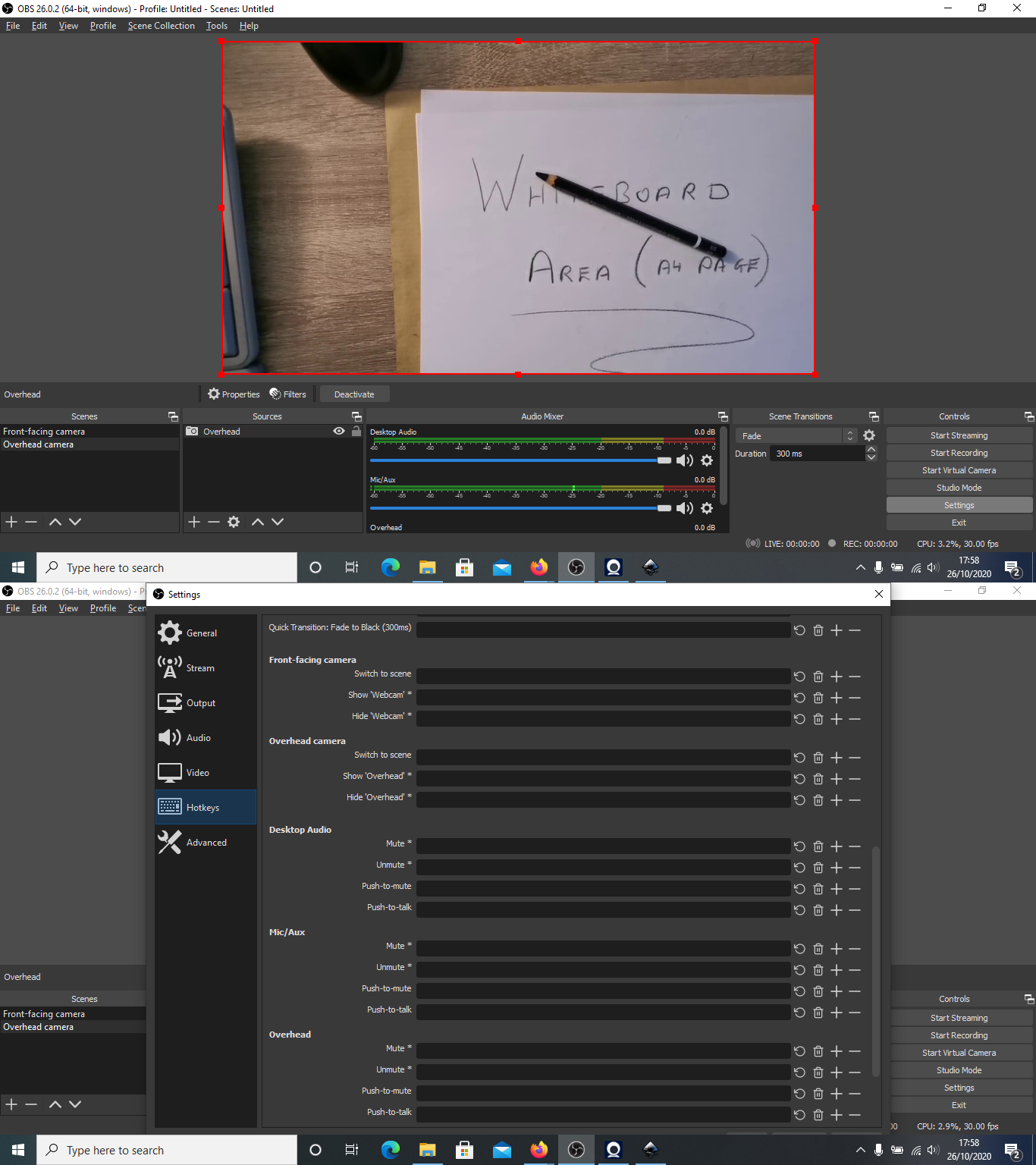
On the keyboard I am using there is a keypad available which I have found to be the most useful set of keys to use for the hotkeys. I am assigning NUM1 and NUM2 to Front-facing and Overhead camera. Once these are set, apply the changes. Now your key presses should change the preview in OBS.
Virtual Camera
The next step is to output the OBS preview using the virtual camera option (additional installation required on MAC) so that other programs can use the video stream as an input. This is done using the “Start Virtual Camera” button under controls on the right-hand side of the OBS interface.

Example application
LPC1114FN28/102 programming on macOS
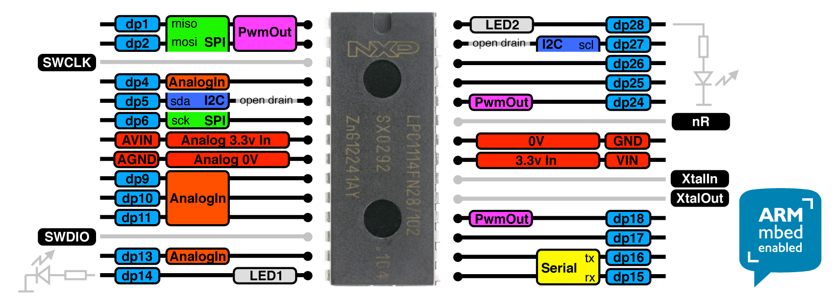
I am currently tutoring on a microprocessors module in TU Dublin where students have the opportunity to learn about hardware and software aspects of microprocessors and microcontroller systems development. The microprocessor we are currently using is the LPC1114FN28/102 processor, an ARM Cortex M0 microporcessor in a 28 pin dual inline package format. A pinout is shown here.
Currently, we are programming these using a hardware debug tool that supports Serial Wire Debug, and a USB to serial converter, which is setup initially for Windows devices. Although, some students do prefer to use their own devices and in certain cases these are Mac operating systems so I’ve decided to outline the steps I have taken to allow for the programming of the LPC1114FN28/102 processor on a macOS.
Homebrew package manager
I typically use Homebrew where possible to maintain a list of any packages I download and install on my own macOS. Homebrew is a package manager that allows users to download and install packages using the Terminal program on a macOS.

There is a brilliant tutorial on the Homebrew website about how to use their tool via Terminal and I will try to talk you through the relevant steps here. First, to install Homebrew open a new terminal and run the following command.
/usr/bin/ruby -e "$(curl -fsSL https://raw.githubusercontent.com/Homebrew/install/master/install)"
This will allow you to use brew commands now, for example I used “brew” to “search” for installation files for “inkscape”.

Once Homebrew is installed we can move onto the next part, installing the GNU toolchain which will have the compiler used for converting the source files.
GNU toolchain installation
The GNU toolchain can be installed manually by downloading the require libraries, extracting the correct location, and by setting the required path, or we cal let Homebrew do all the hard work for us. A set of users on GitHub have provided the required commands to use brew to install the GNU toolchain, and these commands are,
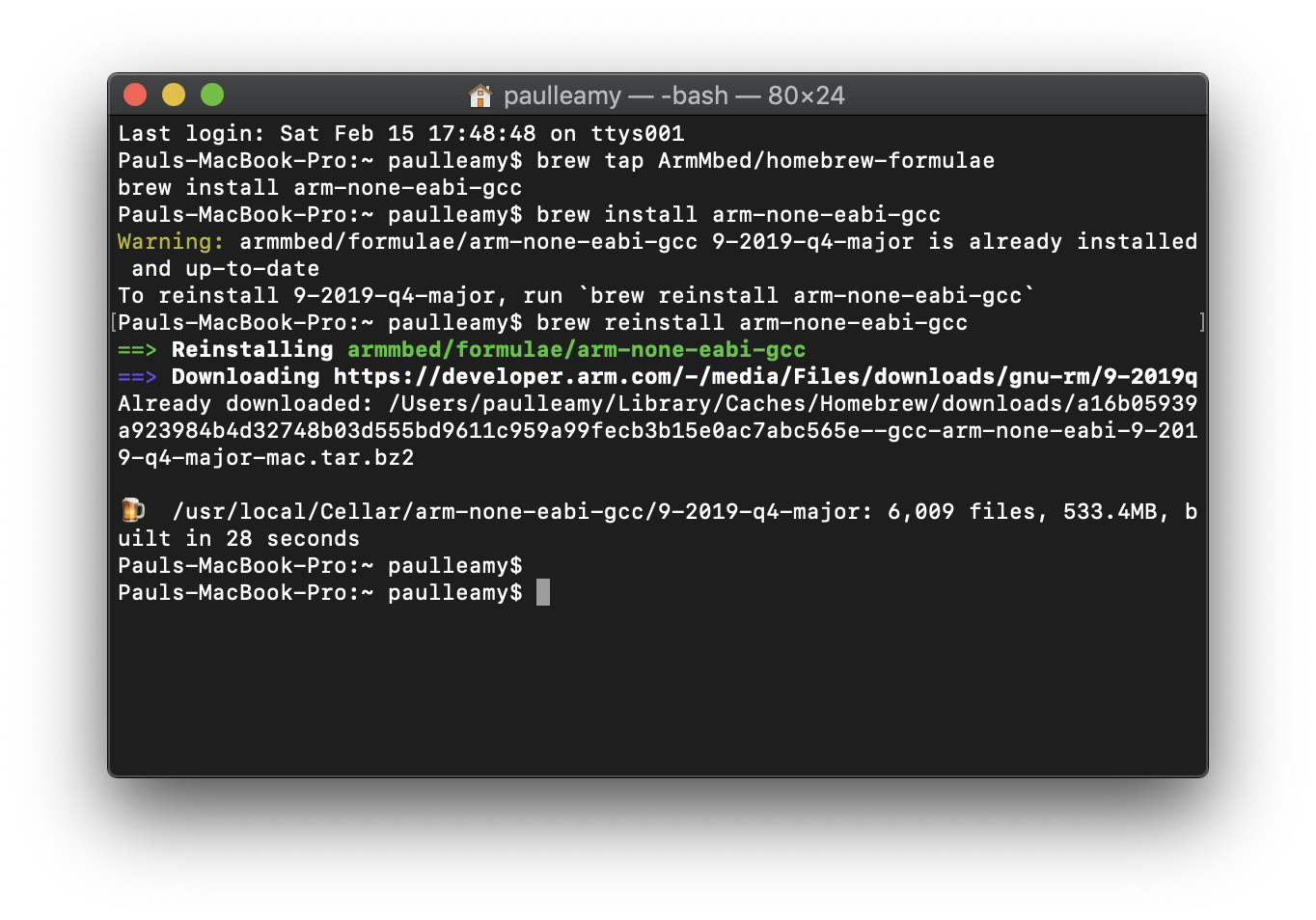
brew tap ArmMbed/homebrew-formulae
brew install arm-none-eabi-gcc
If installed successfully, Homebrew will tell you with a terminal screen similar to this (notice I reinstalled for demonstration purposes).
You can test at this point to see if the compiler can be run from the terminal screen by using the following command.
arm-none-eabi-gcc
Without specifying a source file and arguments you should get an error, see my terminal scree for example.

lpc21isp downloader installation
To download the code via the USB to serial converter, an in-circuit programming (ISP) tool is required. This is used to download the machine code produced with the GNU toolchain via a specified serial port. This link provides an explanation on how to do this with Homebrew! The commands are shown below.
ruby -e "$(curl -fsSL https://raw.githubusercontent.com/Homebrew/install/master/install)"  /dev/null
brew install lpc21isp
With the lpc21isp installed we can begin programming our microprocessors!
An example of the code used to compile a source file and download the .hex to the microprocessor could be as follows.
arm-none-eabi-gcc -static -mthumb -g -mcpu=cortex-m0 *.c -T linker_script.ld -o main.elf -nostartfiles
arm-none-eabi-objcopy -g -O ihex main.elf main.hex
lpc21isp main.hex /dev/ttyUSB0 9600 12000000
I ran these commands in my own terminal with the appropriate files in my current directory. The result is shown in the screenshot below.

Some additional info
Two more points that I think will be useful if you decide to program your LPC1114FN28/102 with this method.
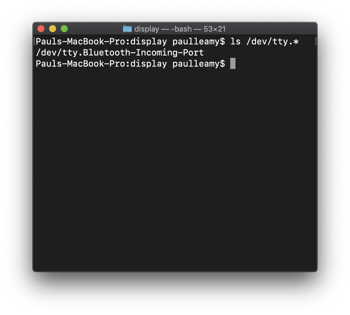
First, the view the open com ports on a macOS, use the following command.
ls /dev/tty.*
Second, you may need to install the drivers for your own USB to serial converter, which can be down via Homebrew too!
Progress Report
Well!
Apologies for the delay in keeping people up to date in C.A.K.E HQ, but I’m sure like everyone else, I’ve been kept busy with other projects and work! But let’s get on with how things have been going! Since my last post, there was a few problem’s encountered in relation to our original design for the sumo bot but as well as that much progress has been made with the new design.
The original design was to construct the “Monolith” like bot Gian drew up in Solidworks! I undertook the construction of the chassis, wheel mount and the motor/wheel connection. I drew up some scaled blueprints for the design on Solidworks,

These helped give an idea on where to mount the four wheels and the motors, along with the circuit board, colour sensors and rangefinders. Below is a picture of what the chassis was beginning to look like, The middle was going to contain the circuit board and battery pack, the top would hold the rangefinders and the bottom would hold all for motors and wheels within the the 15cm squared base,

The next step was to find a way to mount the four small motors shown in my last post to the chassis. This is where thing took a bad turn! After I spent two days of trying to mount the motors to the chassis by drilling and trapping the chassis or by means of a nut or bracket the decision to scrap these motors was made! This would probably have been the case even if a method of mounting the motors was found, since the motors themselves weren’t really meant for driving a wheel directly and even with the adapters I talked about in my last post, the connection between motor and wheel still wasn’t very secure. Unfortunately this meant that the use of our new motors and the “Monolith” design would have to be scraped and a new design decided on quickly since time was running out.
Luckily, we still had the motors and chassis used in the race to the wall. Using this set up I began construction in the workshop with Chris on the new fighting bot. We began by removing the front wheels so the bot could be steered in either direction with the two back wheels. Using some aluminium from home I fabricated a bracket which I attached to the race bot chassis. This gave a suitable surface to attach some old metal “danger notices” , bent into the shape of a wedge, to the wheels. The result is shown here,


I spent most of today putting together the sensors needed for the robot. The rangefinders are now attached to the brackets so they can be bolted to the top of the robot(pics will be up soon), To save on space inside the robot, I improved on Gian’s original idea of turning the colour sensors form a four wire device into a tree wire. Instead of using a piece of veroboard to hold the resistors needed for the sensor I soldered them directly in series with the wires and brought out the necessary lead from the phototransistor, then covered the wires in heat shrink to insulate them from each other. The picture below shows the heat shrink near the sensor, along with plugs attached at the end of the wires so it can be easily connected to Gian’s circuit board,

I done the same with the Infra Red L.E.D.s used for data transmission from the robot to a computer connected to the IR receiver,

The circuit board will be attached to the flap shown in the pictures above and the battery pack will be mounted inside also. To finish of the chassis side panels will be added for extra protection.
I should have one more post up before the fight on Thursday with the finished bot!
Good luck to everyone!
Wheely Big Problem!
Alright everyone!
So with my last post it seemed that the issue of mounting the new wheels to the new motors was sorted, but after trying this method out it was easily seen that using the pen tip as a mount was to flimsy so a new approach was needed!
With a little bit of research into motor shaft mountings and what not I came across a piece known as a coupling adapter which is essentially a way of increasing your motor shaft diameter. It works by mounting a larger shaft on top of the original shaft which is then held in place by grub screws, here is a few pics of the old and new shaft, and the coupling adapter in one of the wheels,


Hopefully this will solve this issue once and for all!
Back at it!!!
Hello again!
Apologies for the lack of updates in the last few weeks! Work has been piling up and unfortunately not a whole lot of was done in terms of robot building. Lots of ideas were being thrown around here at C.A.K.E HQ. Gian came up with an amazing looking idea for the body and chassis of the fight bot and I must admit I’m very impressed. Looks spectacular and cant wait to get it built!
The overall design our robot is going to incorporate the use of two Sharp IR rangefinders to act as a means of locating the opponent during a bout. The idea is to use two sensors with their beans crossed. If one beam is broken by the presence an opponent’s robot, our robot can be turned in a particular direction and stay turning until the next beam is broken thereby leaving our robot facing head on towards the opponent. This picture gives an idea of how the sensors could be positioned.

The sensors work off a 5v supply with a varying voltage out depending on the distance that the object obstructing the infra red beam is from the sensor. I carried out a small experiment in class today to see the response of the sensor with various materials to see if different surfaces affect the output of the sensors differently. This graphs plots the response of the sensor.

The graph shows the response of the sensor using a paper and metal surface. There is a few small variations in some points in the graph but both surface led to similar results with the trend following what was expected. These results will give an idea of what to threshold to set in the code depending on the design we end up using on the robot.
Gian managed to source a new set of motors that are about the size of a AAA battery!!! That’s including the motor and gearbox. Very neat indeed. The main issue that arose with using these motors though was the fact that the diameter of the shaft is no more than 1.5mm and finding wheels with a matching diameter in the centre is very hard indeed. Since the wheels we plan on using have a 4mm hole an adapter is going to have to be fabricated before the motors can be attached to the wheels. While discussing how to manufacture a metal adapter in class today, the combination of Gian and I pulling apart Chris’ pen(which he left in one of the wheels) in boredom led to the discovery of a free, pre made, perfect fitting adapter in the form of the nib of a pen and the inner tube in which the ink is kept. Eureka! By cutting the tube short and inserting into the middle of the wheel a convenient hole is left for the motor. Along with a drop of super glue and some epoxy cement, the wheels can be attached. JOB DONE!
Here is a few pics of the the motor and and the part of the pen we plan on using as an adapter,


Took a quick video of the driver powering all four motors, apologies for the poor quality. Chris should have a better video up pretty soon,
Until next time,
G’luck!
Race Done!!!
YO!
Well the race is over and done! Well done to the lads from Sparta, great robot and great win, amazing sight to watch during the last few races for the battle of first place.
I must admit I’m upset we didn’t win but delighted with the performance and time we achieved during the competition with C.A.K.E. A smart bit of programming managed to knock off a couple of valuable seconds thanks to Gian and I picked up a good few tips myself from the other teams.
Can’t wait for the next part of the competition to get under way and I am really looking forward to getting our fighting bot up and running.
Good luck everyone!!!
